PLCopen 2-Axes Template - ST
This template project contains a two-axis template for getting started with a KAS application.
- It contains key project elements that save development time.
- The templates are designed to add code to the programs and Control Panels in the template or to new templates.
- A project can contain many programs, and each program can be written in FBD, FFLD, IL, SFC or ST programming languages.
- Additional axes can be added to the template applications that have three, four, five, or more axes.
PLC Programs
This 2-axis PLCopen template has a ST program (called Main) that initializes, starts and runs the motion. The motion includes single axis jogging, incremental and absolute moves, and gearing motion between axes. Also included are controls to enable/disable the drives, clear faults, and display fault and axis position information in the Control Panel. A second program, FaultMonitor, reads the drive fault and position information.
The programs are commented to ease their use.

Figure 1: PLCopen Template with ST - Main
Also included are three subprograms (MCFB_AKDFault, MCFB_AKDFaultLookup, and MCFB_Jog) that are Kollmorgen UDFBs and can be found in the Project Library section of the IDE.
The template contains two PLCopen Servo axes where User Units, Update Rate, Rollover Position, and Axis Limits are defined as:
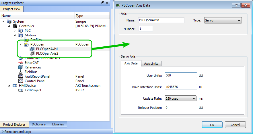
Figure 2: PLCopen Template - Motion
See Axis Data Parameters for more information about PLCopen axis parameters.
The template contains a Control Panel which works inside of the IDE when running a project.
It is a useful tool to run and debug programs.
Control Panel Screens
The Control Panel has these screens:
- Control Panel
- Fault Report Panel
Control Panel Sections
The Control Panel has these sections:
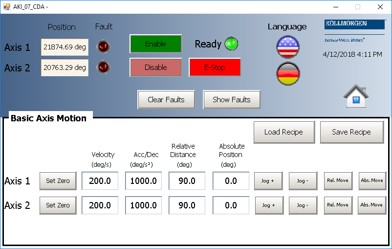
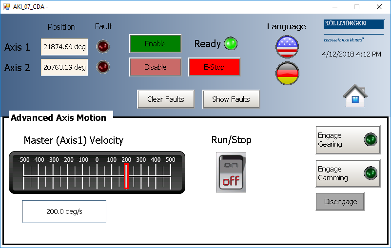
- Multi-Axis Commands: Controls motion and shows gearing.
- Single Axis Motion Commands: Shows motion at the single axis level and resetting the axis position.
- Axis Status: Shows basic axis information.
See Design the HMI with the Internal Editor for more information.
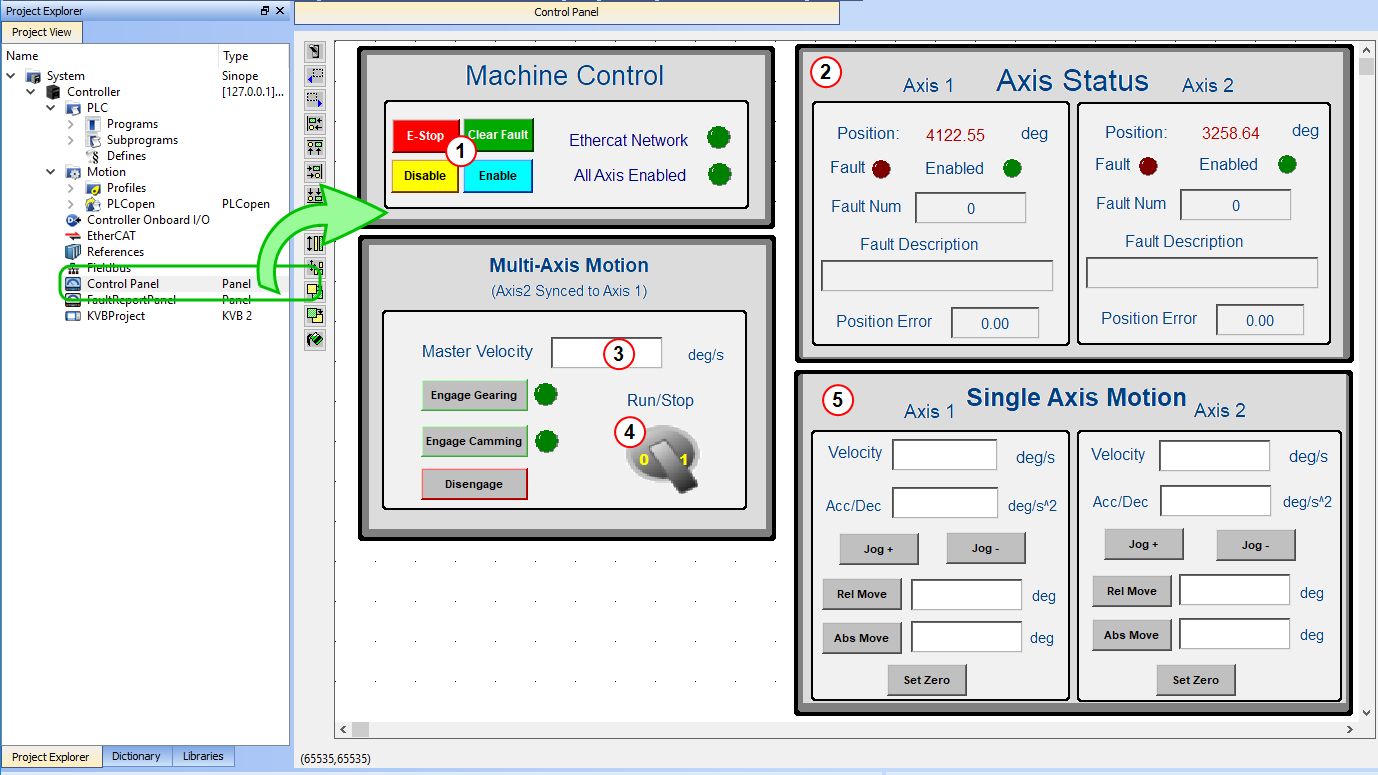
Figure 3: PLCopen Template - Control Panel
| Call out# | Description |
|---|---|

|
Allows for enabling or disabling the axes. After an emergency stop, select the Reset and Enable commands before running the axes. |

|
Displays the actual position for each axis. |

|
Used to set the speed. |

|
Start or stop the motion on the condition that the axes are enable. The green light must be switched on. |

|
Control the axis motion. |
Fault Report Panel provides more detailed information about when a drive fault occurs.
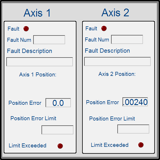
Figure 4: PLCopen Template - Fault Report Panel
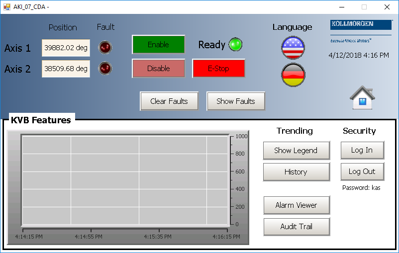
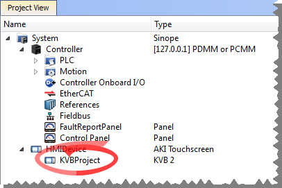
Included in the project template are HMI screens for the AKI terminals created in the KVB (Kollmorgen Visualization Builder) environment.
- The KVB software is a separate installation from the KAS-IDE.
- In KAS-IDE, double-click the KVB Project item in the project tree to open KVB.
The project can be run in the KVB programming environment after the KAS-IDE program has started running.
Click on the Run button in the Project ribbon to start the program.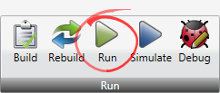
These screens, localized in English and German, are included that duplicate the controls on the IDE Internal Control panel screens.